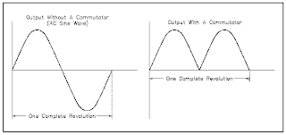
Commutation is the positioning of the DC generator brushes so that the commutator segments change brushes at the same time the armature current changes direction. More simply stated,commutation is the mechanical conversion from AC to DC at the brushes of a DC machine, as shown in Figure

Commutation is the process by which a dc voltage output is taken from an armature that has an ac voltage induced in it. You should remember from our discussion of the elementary dc generator that the commutator mechanically reverses the armature loop connections to the external circuit. This occurs at the same instant that the voltage polarity in the armature loop reverses. A dc voltage is applied to the load because the output connections are reversed as each commutator segment passes under a brush. The segments are insulated from each other.
In figure , commutation occurs simultaneously in the two coils that are briefly short-circuited by the brushes. Coil B is short-circuited by the negative brush. Coil Y, the opposite coil, is short-circuited by the positive brush. The brushes are positioned on the commutator so that each coil is short-circuited as it moves through its own electrical neutral plane. As you have seen previously, there is no voltage generated in the coil at that time. Therefore, no sparking can occur between the commutator and the brush. Sparking between the brushes and the commutator is an indication of improper commutation. Improper brush placement is the main cause of improper commutation.
 This entire commutation is done by the commutator in D.C Generators. Now we will see how the commutator performs commutation.
Commutator Action
The commutator converts the AC voltage generated in the rotating loop int
 o a DC voltage. It also serves as a means of connecting the brushes to the rotating loop. The purpose of the brushes is to connect the generated voltage to an external circuit. In order to do this, each brush must make contact with one of the ends of the loop. Since the loop or armature rotates, a direct connection is impractical. Instead, the brushes are connected to the ends of the loop through the commutator.
In a simple one-loop generator, the commutator is made up of two semicylindrical pieces of a smooth conducting material, usually copper, separated by an insulating material, as shown in Figure . Each half of the commutator segments is permanently attached to one end of the rotating loop, and the commutator rotates with the loop. The brushes, usually made of carbon, rest against the commutator and slide along the commutator as it rotates. This is the means by which the brushes make contact with each end of the loop.
Each brush slides along one half of the commutator and then along the other half. The brushes are positioned on opposite sides of the commutator; they will pass from one commutator half to the other at the instant the loop reaches the point of rotation, at which point the voltage that was induced reverses the polarity. Every time the ends of the loop reverse polarity, the brushes switch from one commutator segment to the next. This means that one brush is always positive with respect to another. The voltage between the brushes fluctuates in amplitude (size or magnitude) between zero and some maximum value, but is always of the same polarity (Figure). In this manner, commutation is accomplished in a DC generator.

One important point to note is that, as the brushes pass from one segment to the other, there is an instant when the brushes contact both segments at the same time. The induced voltage at this point is zero. If the induced voltage at this point were not zero, extremely high currents would be produced due to the brushes shorting the ends of the loop together. The point at which the brushes contact both commutator segments, when the induced voltage is zero, is called the "neutral plane."